We are now required to collect sales tax in several states. Learn more about tax exempt status for your business.
Magnets can reach through walls! You may know this from performing a simple magnetic magic trick at the kitchen table. You can make a magnet sitting on top of the table move around by manipulating a magnet underneath the table. It’s a great trick that never fails to fascinate.
This same principle is used in magnetic couplings. An array of magnets can spin a shaft, reaching across a small gap to transmit torque or force.
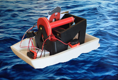
To demonstrate, we’ve made a simple boat that uses a magnetic coupling to transmit power through the hull of a boat. The power source comes from a motor inside the boat, driving magnets to spin a propeller on the outside – all without drilling a hole in the hull of the boat!
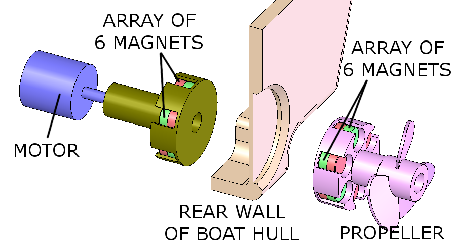
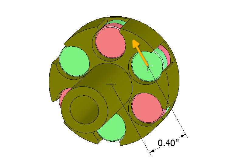
How does the magnetic coupling work? By using magnets that attract towards one another across a gap. For this demonstration, we chose a common configuration where 6 magnets are arranged about the shaft’s axis, with alternating poles facing out. This is attached to the motor, which spins it.
As you look at the face of the assembly, the poles facing you alternate between north and south. This configuration seems to provide the most strength.
The same configuration is chosen for the opposite part, the propeller sitting on the opposite side of the hull.
When one part spins, the other follows
Let’s get to the good part first: How does this thing work in an actual boat?
We 3D printed a number of parts to make a simple demonstration. It uses an old DC cooling fan salvaged from a broken printer to spin the shaft. Because the cooling fan spins so fast, we made a series of pulleys to convert the rotation to a slower speed. The clunky, rubber-band enabled drive system won’t win any boating awards, but it works well enough for this quick demo.
When the fan spins, it turns the array of magnets on the inside of the boat. Because the magnets reach through the hull, this motion spins the propeller.
While our demo might not be all that impressive, you can see how useful the idea might be. The ability to transmit motion through a sealed wall has a lot of useful applications. Spinning a boat’s propeller seemed an obvious example, but we’ve heard from folks who make food processing equipment that use this sort of thing to stir things inside a sealed stainless steel container.
Perhaps even more common, engineers use this kind of coupling on machinery that doesn’t even have a wall to reach through. Using a magnetic coupling across an air gap can be a great way to reduce vibration transmitted through a drive system.
Ultimately, no matter how successful your magnetic coupling design, there will be a torque limit. There’s an upper limit to how much torque can be transmitted by such a device. If you try to spin one side harder, the magnets will “slip.” While this is often seen as a downside (I need a stronger coupling to transmit my power), it can also be a feature. Limiting the amount of torque applied to a motor can protect it from damage.
That’s a tough one. We don’t have a simple answer for this question. We’re definitely not experts on this subject. There are a lot of factors involved, and they’re all interrelated in interesting, complex ways. This includes:
In practice, careful experimentation, iteration and measurement are the best methods to achieve the desired performance. From our experience, we can only suggest a way to get a ballpark estimate of what you might expect. Trying to calculate the slipping torque for setups like these seems to be very difficult.
We really didn't know what magnets would be right for the boat we made. We designed around 5/16" diameter magnets like the D52 or D54. With the final setup, it turned out that a series of six D52 magnets attracted towards one another too much. The friction of these parts sliding on the boat's hull proved too much for the weak motor to overcome. In the end, we only used two D52 magnets on the propeller to reduce the pull force across the gap. We just left the other holes empty.
Here's one way to estimate how much torque might be provided by a given array of magnets:
This method is far from perfect, but can be helpful in the initial stages of a design to provide a ballpark estimate. It can be challenging to have a gut feel for what looks right: Do we need modest ¼” diameter magnets, or powerful 1” diameter magnets? This way of looking at it can provide a rough starting point for your magnetic coupling experimentation.
For the truly adventurous, you can download the 3D model files for the 3D printed parts we used for this boat demonstration. We created them ourselves for the demo, and they are far from perfect. The boat's not fast, you need a really powerful 80mm fan, and the propeller needed a bit of filing to fit in the back of the boat. It's a classic case of everything looking pretty on the computer screen, but somehow not quite assemble-able in reality. If you create something nicer, please send us a picture!


 Cart
Cart