We are now required to collect sales tax in several states. Learn more about tax exempt status for your business.
We describe the steps involved in manufacturing neodymium magnets, with some notes on what this means for practical magnet users.
The basic compound for most Neodymium magnets is Nd2Fe14B. In practice, the actual chemical reaction used can be more complicated. A commonly used reaction is:
57 Fe + 8 B + 10 Fe2O3 + 7.5 Nd2O3 + 52.5 Ca -> Nd15Fe77B8 + 52.5 CaO
Note that the powder formed by this reaction is slightly different than the Nd2Fe14B ratio. Magnets are often made both Nd-rich and B-rich, where finished magnets typically contain non-magnetic bits of Nd and B in the grain, within which are highly magnetic Nd2Fe14B grains.
For higher temperature magnet grades, additional elements are added. When small amounts of Iron (Fe) are replaced with Cobalt (Co), the properties improve at elevated temperatures, but the intrinsic coercivity decreases. If small portions of Neodymium (Nd) are replaced with Dysprosium (Dy), the intrinsic coercivity is improved, but the maximum energy product (BHmax, a good measure of a magnet's strength) decreases. It is common to use both Co and Dy together.
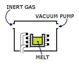
The chemical reaction described above occurs in a vacuum induction furnace. The products are heated by creating electrical eddy currents through it, all in a vacuum to keep contaminants out of the reaction.
Jet milling turns the resulting material into a powder with a very small particle size. The average particle size is on the order of 3 micrometers.
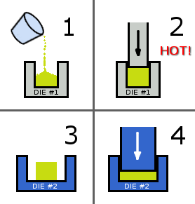
The powder is pressed together to form a solid that has a preferred magnetization direction. In a technique known as die-upsetting, the powder is pressed with a die into a solid at elevated temperatures of about 725°C. The solid is then placed in a second die, where it is compressed to a wider shape that's about half it's original height. This aligns the preferred direction of magnetization parallel to the pressing direction. For some shapes, there are methods that include a fixture that generates a magnetic field during pressing to align the particles.
Sintering is a common process in powder metallurgy. The material is compressed at elevated temperatures (as high as 1080°C) below the material's melting point, until its particles adhere to each other.
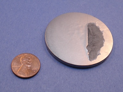
The sintered magnets are cut to the desired shape using a grinding process. Less commonly, complex shapes are made with electric discharge machining (EDM). Because of the high material cost, material losses due to machining are kept to a minimum. No effective means of recycling the waste has been developed.
The individual magnets are electroplated with three layers: nickel, copper and nickel. This is necessary because un-plated neodymium magnets are highly prone to corrosion, and will quickly lose their magnetic properties in the presence of moisture.
At this point, the magnets have a "preferred" direction of magnetization, but they are not magnetized. They are placed in a fixture that will expose the magnet to a very strong magnetic field for a brief moment. It's basically a big coil of wire surrounding the magnet(s). The magnetizing equipment uses banks of capacitors and a really huge voltage to get such a strong current for a brief instant.
The quality of the resulting magnets is inspected for a variety of properties. A digital measuring projector verifies the dimensions. A coating thickness measurement system using x-ray fluorescence technology verifies the thickness of the plating. Periodic testing in salt-spray and pressure-cooker tests also verify the performance of coatings. A hysteresigraph measures the BH Curve of magnets, which confirms that they are fully magnetized as expected for the magnet's grade.
Peter Campbell, Permanent Magnet Materials and their Application, 1994
J.M.D. Coey, Rare-Earth Iron Permanent Magnets, 1996
R.W. Lee, E.G. Brewer and N.A. Schnaffel, Processing of neodymium-iron-boron melt-spun ribbons to fully dense magnets, IEEE Transactions on Magnetics, 1985


 Cart
Cart