
Magnetic Shake Flashlight
How can you guys have so many articles about magnets, yet you haven't talked about generating electricity? Magnets can be used to make electricity! In this article, we will generate electricity in a shake flashlight that is powered by a moving magnet.
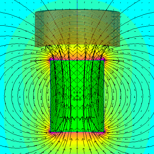
Faraday's Law: Moving magnets near a coil of wire yields electricity
From HyperPhysics (an old but good site describing physics concepts):
Any change in the magnetic environment of a coil of wire will cause a voltage (emf) to be "induced" in the coil. No matter how the change is produced, the voltage will be generated. The change could be produced by changing the magnetic field strength, moving a magnet toward or away from the coil, moving the coil into or out of the magnetic field, rotating the coil relative to the magnet, etc.
In our case, we're going to move a magnet back and forth through a coil of wire. Each time the magnet moves from one end of the tube to the other, the magnetic field inside the coil will reverse direction (twice).
The voltage generated is proportional to the quick change in the magnetic field direction, multiplied by the number of turns of wire. Voltage generated = (number of wire turns) * (change in magnetic field strength per second).
Build a coil
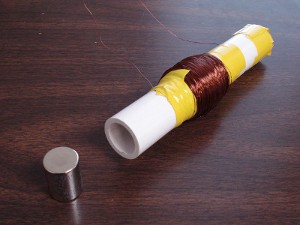
We take a generous supply of magnet wire, and wrap it in many turns around a non-magnetic tube. For this example, we chose 3/4", schedule 40 PVC pipe sized for a DCX0 3/4" diameter x 1" tall, axially magnetized cylinder magnet.
Magnet wire is just like regular wire, except that the insulation is very thin. This is great for coils, windings or transformers, because it lets you get more turns in a given amount of space. In our example, we used thin, 30 gauge wire.
UPDATE: We now offer 30 gauge Magnet Wire like this. See MW30-4.
We used an electric drill attached to the tube to spin a large length of wire around it, for many turns. Sorry, we forgot to count how many!
Watch the flow of electricity with LEDs
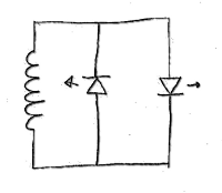
An LED is a diode that emits light when electric current runs through it. Like all diodes, it allows current to flow through it in only one direction. Before going any further, let's use a pair of diodes to test our coil assembly to see if it makes any electricity.
Our test setup is shown in the circuit diagram below. Any current generated in the coil will flow through one of the two LEDs, depending on it's direction.
A few circuit improvements for a better flashlight
Now, let's add a few more things to our circuit to transform this blinking light into a steady, usable light source.
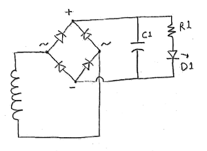
1. First we add a diode bridge that will take the alternating electrical output of our coil, and get it flowing in one direction. See Diode Bridge (or Graetz circuit) for a good description of how this functions.
You can make a diode bridge out of four individual diodes. We chose a package that combined them into one unit.
With this diode bridge, we can light just one LED since all the electricity will flow in one direction.
2. What we need now is a storage device to smooth out the current, and provide a steady flow of electricity instead of the short bursts provided from our coil. A capacitor (C1) functions exactly this way. Without the capacitor, the LED would blink on and off like a strobe light.
Some human-powered flashlights use rechargeable batteries to store more power. We just used a capacitor to smooth the current out.
3. We also use a resistor (R1) in series with the diode. In this case, we used a 300 Ohm resistor. This limits the flow of electricity through the diode. The big power resistor used in the video below isn't really necessary -- we just had this one handy.
Watch the finished prototype in action
What is the total output of our setup?
This is great! How much power does this generate? The short answer is: enough to light an LED, but not a lot. The main reason for using an LED as the light source is that it doesn't take much electricity to generate light with LEDs. If you used a regular incandescent bulb, the light would look pretty weak.
If you have access to an oscilloscope, you can measure the output power of this circuit. Assuming you don't, you can measure the power coming out of it with a simple multi-meter. We recorded a test of the flashlight, while showing the voltage across the resistor with a multi-meter. This gives us some measure of the actual useful energy produced from our test setup, after losses from the bridge diode and any inefficiencies associated with storing power in the capacitor.
The total energy shown in the graph (in the video below) tops out at about a third of a Watt. It represents the energy dissipated in both the resistor and the LED.
I want to make my own flashlight. What variables should I consider?
There are many factors that go into a device even as simple as this, plus they all interrelate with one another. Some key variables include:
- The number of turns of magnet wire. The voltage generated is directly related to the number of turns. In a perfect, uniform magnetic field, doubling the number of turns should double the voltage. Of course, as you keep adding turns, you are both getting farther away from the magnet, and increasing the distance through which the current must travel. It's definitely a case of diminishing returns. How much more power would we see if we increased the number of turns?
- The wire gauge. We used 30 gauge, but you could consider other wire thicknesses. The thicker the wire, the more current it can carry with less loss. The thinner the wire, the more windings you can fit close to the magnet.
- Magnet size. We used a DCX0, because we thought it would make a nice sized field, and work well with a pretty big coil of wire. You might consider a smaller magnet, or go even larger. Larger magnets will work more effectively with even bigger coils of wire.
- LEDs. We chose a few LEDs off the shelf because they were inexpensive and available. LEDs can vary wildly in how much light they produce from a given amount of electricity. Some are weak and meant simply as indicator lights. Newer LEDs are being used in lighting applications, sometimes replacing traditional light sources. There are also interesting tradeoffs between bright, narrow beams and dimmer, wide beams of light.
- Mechanical Packaging. Certainly the mechanical packaging of such a device can be made better. We added thin DC2 magnets on either end of the tube, repelling the magnet inside. This acted as springs on either end to keep from wasting energy, slamming into the ends of the tube. Other features might include an on/off switch, something to protect the magnet from scraping off it's nickel plating, better optics, and whatever else you want in a flashlight.
- Other storage devices. The capacitor works great to store some electricity, but it doesn't hold much. Many shake or hand-crank flashlights use a rechargeable battery as a storage device. These can allow you to store much more electricity. A small rechargeable battery can go a long way.
- Better current control. The resistor we put in series with the LED is an inexpensive, simple way to regulate the current through it. There are other ways to control the current. Advantages of other solutions might include using less power, and keeping the constant current even as the capacitor/battery voltage drops.