

Eddy Current Brakes
A Closer Look at Eddy Currents
Some of the most popular magnet demonstrations highlight eddy currents. Whether it's magnets falling through a copper tube or falling against a flat plate, strong magnets move slowly when next to a conductor.
We took a brief look at this in our original Eddy Currents article. It's about time for a deeper look. We'll explore a formula that calculates the eddy current forces, and try to merge that theory with experimental testing. We hope to figure out how to estimate these interesting forces.
What is it good for?
Other than viral magnet videos, what are eddy currents good for? Are they actually useful? You bet. Our original Eddy Currents article highlighted a few applications, including safety brakes for a roller coaster. Though less glamorous, the same mechanism can be used on elevators or any rail system for a safe, un-powered brake. That's the example we're going to take a closer look at today.
Consider a model roller coaster

We came across a big, thick aluminum plate that was part of an old monitor mount. It's roughly 9 inches (22.86cm) square, and 1/2" (1.27cm) thick. We mounted some wheels to it and slid it down a simple ramp.
We can predict this rolling motion quite well. Newton's laws of gravity and equations of motion work well here.
We added a row of eight 2" x 1" x 1/2" thick BY0X08 block magnets, with alternating poles facing up. They are mounted so that there's just a 1/8" gap between the magnets and the sliding aluminum plate. The changing magnetic field strength induces eddy currents in the aluminum, creating a drag force that slows it down.
What is that drag force?
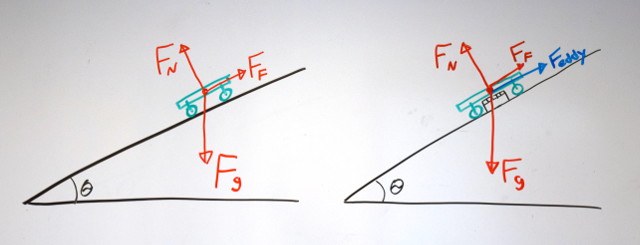
When a magnet moves past that aluminum plate, the metal is exposed to a changing magnetic field. This changing magnetic field induces currents within the aluminum plate. These swirling, circling currents create temporary electromagnets that repel the permanent magnet.
Since we're well known for our Magnet Calculator, we're often asked about this drag force. How can it be calculated? It is much more complicated than pull force. As we understand it, most folks making mechanisms like this often rely on test data.
The goal of this article is to present a formula and test it for a very simple case. This seems like a good approach, breaking it down to the most basic example. It's also a good candidate for a science project! Let's conduct some quick tests to see if we can verify a formula.
Credit where credit is due
We recently came across this paper (found Eddy current magnet brakes): "The Design of Eddy-Current Magnet Brakes." It gets into a lot of detail about optimizing brakes and adjusting fields. What caught our eye was this formula for the eddy current drag force:
Fd = α σ δ Bo2 A v
Where:
- α is a shape factor related to the pole face of the magnet (unitless)
- σ is the conductivity of the metal (S/m)
- δ is the thickness of the metal (m)
- Bo is the field strength in the gap between two magnets. In a small gap between magnets, the field is fairly uniform; that's why it gets away with a single number here. (T)
- A is the area of the pole face of the magnet. (m2)
- v is the relative velocity between the magnets and the conductor (m/s)
Where the rubber magnet meets the
road aluminum

We mounted a length of aluminum extrusion vertically. We created a 3D-printed, plastic trolley to slide down the alumimum pole.
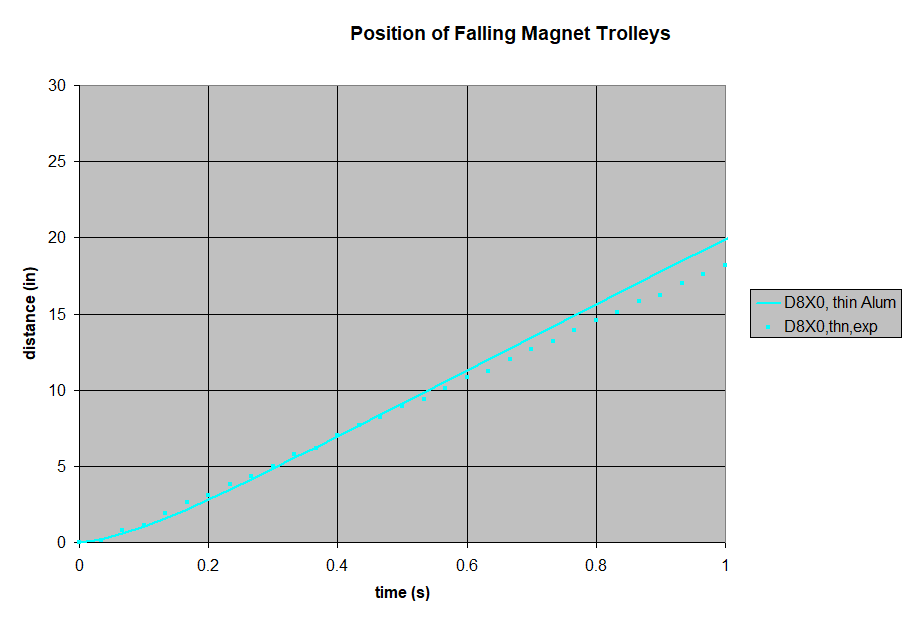
We filmed the freefalling trolley, then analyzed the footage to create a time vs. distance plot. The magnet-less trolley is a good baseline, showing what gravity does without any magnetic drag. At these speeds, air drag is minimal and can be ignored.
Next, we set a pair of magnets on either side of the aluminum pole, held in place by the 3D-printed trolley. We used 1/2" diameter disc/cylinder magnets for all of these tests. By varying the magnet thickness, we can choose the field strength in the gap.
| P/N | diameter (in) | thickness (in) | gap (in) | theoretical field strength (G) |
| D82 | 0.5 | 0.125 | 0.17 | 4,241 |
| D84 | 0.5 | 0.25 | 0.17 | 6,330 |
| D88 | 0.5 | 0.5 | 0.17 | 7,889 |
| D8X0 | 0.5 | 1 | 0.17 | 8,614 |
| D82 | 0.5 | 0.125 | 0.24 | 3,527 |
| D84 | 0.5 | 0.25 | 0.24 | 5,225 |
| D88 | 0.5 | 0.5 | 0.24 | 6,530 |
| D8X0 | 0.5 | 1 | 0.24 | 7,171 |
We filmed a freefall drop of each magnet pair, and plotted the results. To broaden the range of our tests, we repeated all of these with thicker, 1/8" thick aluminum as well. All of these results can be compared to theoretical plots of these falling magnets, using the paper's formula.
For the smaller magnets, we added some steel balls in the trolley so that all our tests used a trolley with the same overall mass.
How did we calculate that theoretical field strength? We used the formula from our Surface Fields article to calculate the field strength for one magnet, at a distance that's half of the gap. That's the midpoint between the magnets. Since the other magnet is doing the same thing, we double the number (assuming magnetic fields add). This might overestimate the field a bit, but it's a good starting point.
What did we learn?
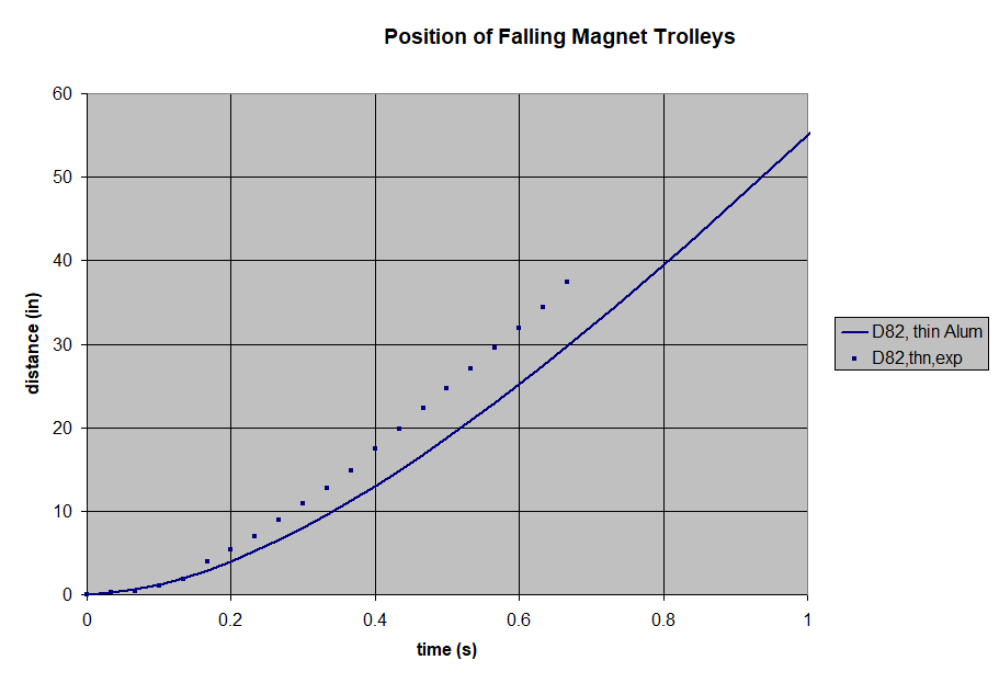
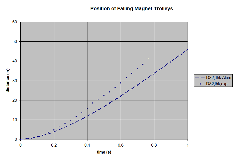
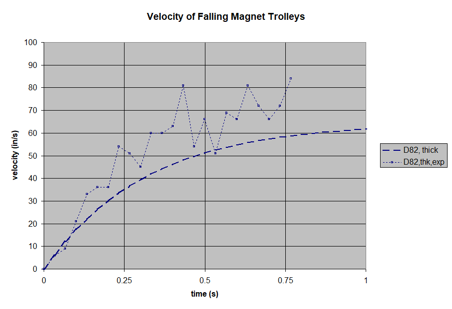
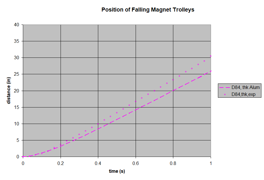
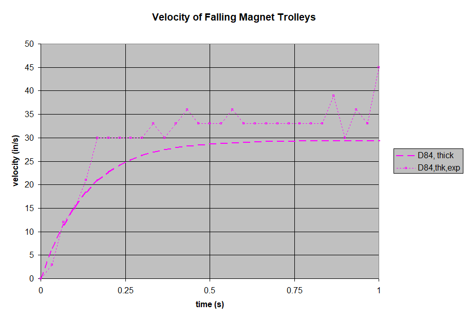
Like all of the thicker aluminum results, the test fell a little faster than the theory predicted.

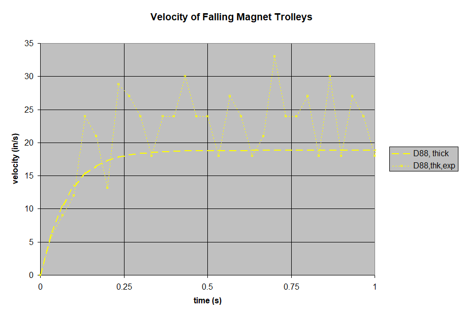
Like all of the thicker aluminum results, the test fell a little faster than the theory predicted.
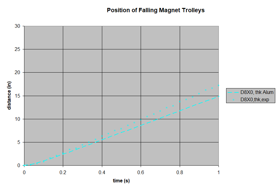
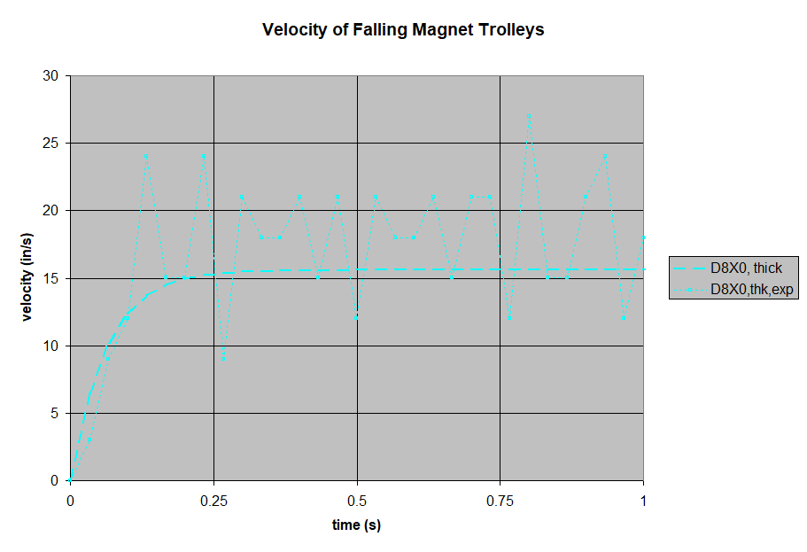
Like all of the thicker aluminum results, the test fell a little faster than the theory predicted.
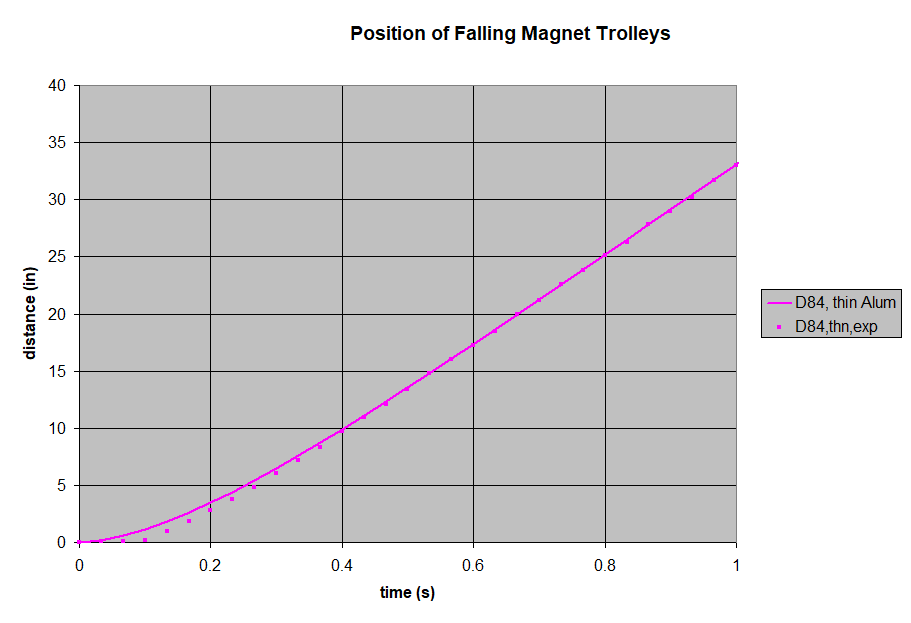
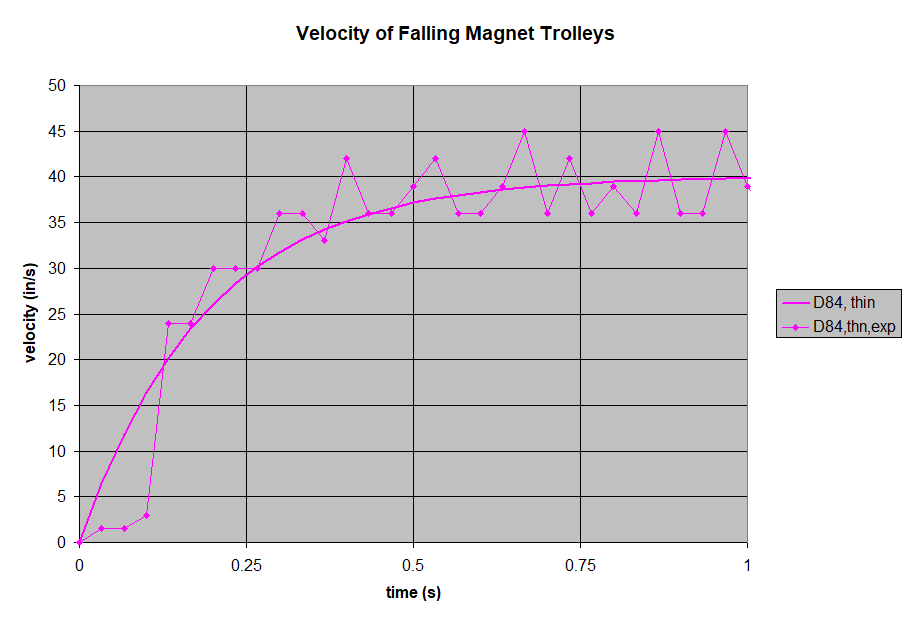
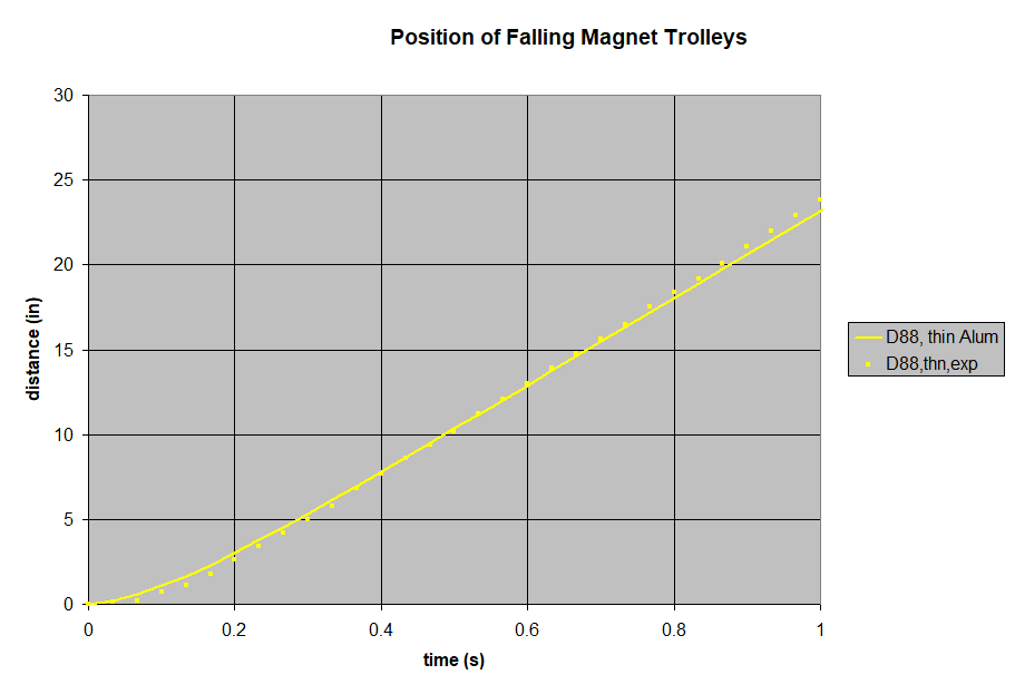
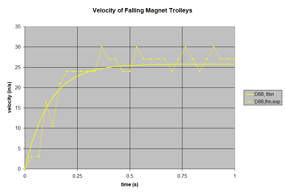
While not perfect, this simple formula is pretty good. It did a decent job of estimating the drag force. The results confirm some overall behaviors you might intuit from the formula:
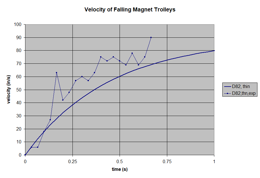
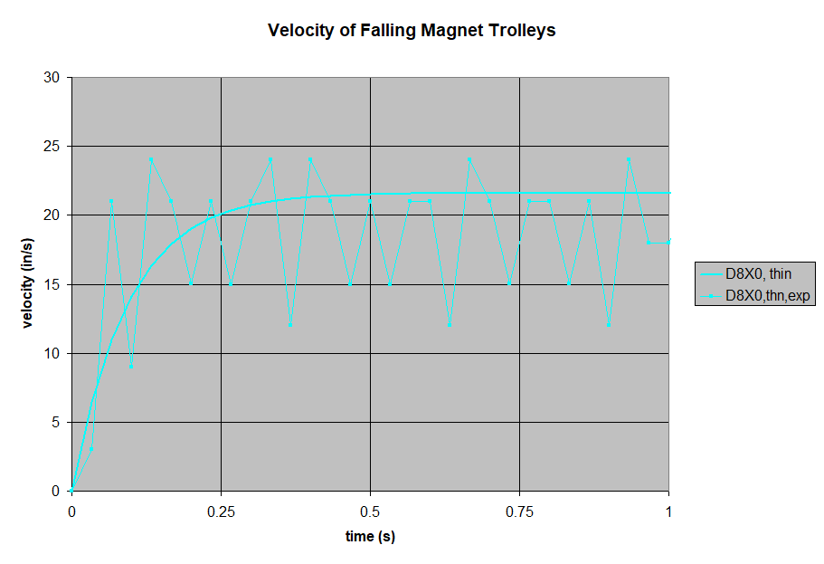
- The trolley's velocity starts out increasing like a magnet-less freefall, but levels out as the drag increases with velocity.
- The trolley's velocity levels out to a steady state, terminal velocity. Like a freefalling skydiver stops accelerating at about 120 mph, so too do these falling magnets reach an eqilibrium. That equilibrium happens at a speed where the drag's deceleration is the same as gravity's acceleration.
- Greater field strength yields greater braking. The braking force goes up with the square of the field strength.
- Greater aluminum thickness yields greater braking.
How might we explain some of the imperfections and discrepancies?
- Experimental noise. Our experiment was pretty quick and dirty, and could probably be controlled better.
- Poor data collection. Though fast, plotting points by looking at frames of footage probably isn't the most accurate choice. A camera's 30 frame per second video isn't very accurate for this sort of data recording!
- Incorrect assumption about field uniformity. The thinner magnets have a greater variation in the field strength in the gap, compared to thicker magnets. This might explain why the formula over-estimated the braking strength of the thinner magnets.
- Other unknowns. For some reason, the theory over-estimated the force on tests with the thicker aluminum pole. Was the material different? Or does the field strength vary more across the volume with the larger gap?
Summary of the simple part
We've gathered some great data of a simplified eddy current brake. We've found correlation between the theoretical formula and the experimental data we recorded.
Can we apply any of this to a more complex setup? How does this apply to that eddy current brake with 8 alternating block magnets we started this article with?
Back to the complex brake
Disclaimer: We're really stretching this formula in this situation. It's not the right tool for the job. It's better for situations like our test, where two magnets sandwich a conductor. It's only in that two-magnets-attracting-across-a-thin-gap scenario where the assumption of a uniform field applies. This rolling aluminum plate only sees magnets on one side, a very different setup indeed.
In practice, one might derive a more complex formula for this complicated situation. It would need to address how the magnetic field strength is not constant over the region. Or, you could use finite element analysis to come up with better numbers. That said, we wondered if applying that simple formula might get us in the ballpark.
We treated this array as 8 separate blocks, each acting as an individual brake when the aluminum roller coaster car is right over top of it. We ignored how that's not really what the combined field looks like. The tough part is choosing a value for the field strength, Bo. The field strength above a single block magnet varies a lot if you're at 1/8" away (the bottom of the aluminum) vs. 5/8" away (the top of the aluminum). Should we pick the average value? We're not sure. Given how the formula uses the field strength squared, that really sets a wide window of expected results.
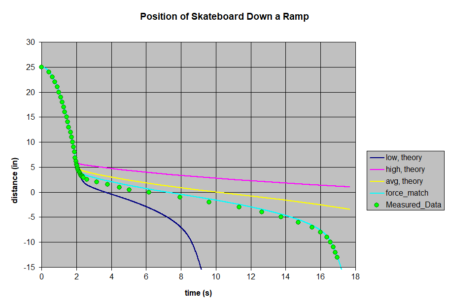
For a single BY0X08 magnet in free space, the field strength might be at 3102 gauss at the lower surface of the aluminum, and 1198 gauss at the far surface. The correct number should be somewhere within this range.
We gathered position vs. time data with the rolling car, just like we did for the falling trolleys on a pole. The position data shows it free-falling at first, but quickly slowing down upon reaching the magnets. The trolley rolls at a fairly constant velocity over the magnets, but accelerates again once beyond the magnets.
We created a long spreadsheet using Newton's equations of motion and this drag force formula to iterate and estimate the position over time. If we pick just the right value for field strength, it matches really well. Of course, it's easy to tweak a theoretical curve to match if you already know the results!
Conclusions
We found the formula to be a good indicator of eddy current braking force, especially in situations where the field strength is uniform. It isn't good enough to accurately predict the force perfectly for all situations. It might be a great way to get within an order of magnitude, but requires some experimental measurements to get exact numbers.
Many real-world eddy current brakes do use setups more like our test, with magnets reaching across one another across a small gap. Is that done because it's easier to calculate? Maybe, but it's a good idea regardless. The braking force gets stronger as the square of the field strength, so designing brakes with higher field strength is a good way to get more braking power.