We are now required to collect sales tax in several states. Learn more about tax exempt status for your business.
Let's make an electric motor that spins using neodymium magnets and wire. No, this isn’t a free energy discussion; we’re supplying energy into the system with a few AA batteries. The real story is about how that electric current is converted into motion.
We’re building a primitive brushless DC motor. It’s not going to win any efficiency or design awards, but we like to think a simple example makes it easier to see what's going on.
The spinning part of an electric motor is called the rotor. Like most brushless DC motors, the rotor has some permanent magnets on it.
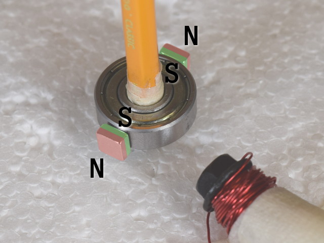
Our rotor spins easily thanks to a 608ZZ bearing stuck on a pencil. This bearing is commonly used in things like skateboard wheels and fidget spinners.
We stuck two B442 magnets on the outer edge of the bearing, 180 degrees apart from one another. Both are oriented with their north poles are facing outward. This is different than most BLDC motors which have alternating poles facing out. This simplification made our electronic circuitry a bit easier.
How do we get this thing spinning? We could just flick it with our finger, but we’re looking for a more magnetic push.
Bring another magnet near one of the rotor magnets, with its north pole facing the north pole of the rotor magnet. Positioned just to one side of the rotor magnet, it will repel that magnet away, setting the rotor spinning.
If we push on the magnet hard enough to spin the rotor halfway around, we can do it again to the next magnet. By pushing on the rotor magnets as they pass by with a magnet held in our hand, we could theoretically get this rotor spinning continuously. We need to bring the magnet close when that magnet swings by, but then pull it away right after. Our hand isn’t that fast, so we’ll need a better idea.
If only we had a magnet that we could switch on and off electronically...
A simple electromagnet consists of a coil of magnet wire wrapped around a steel core. We used 24 gauge, single strand copper wire with a thin, enamel insulation; see MW24-4. A bolt became the steel core after we wound the wire around it.
When we apply a voltage to the coil, it becomes a magnet. With the electromagnet positioned just right, it should push the rotor’s magnet away. Now all we have to do is turn it on and off at just the right moment.
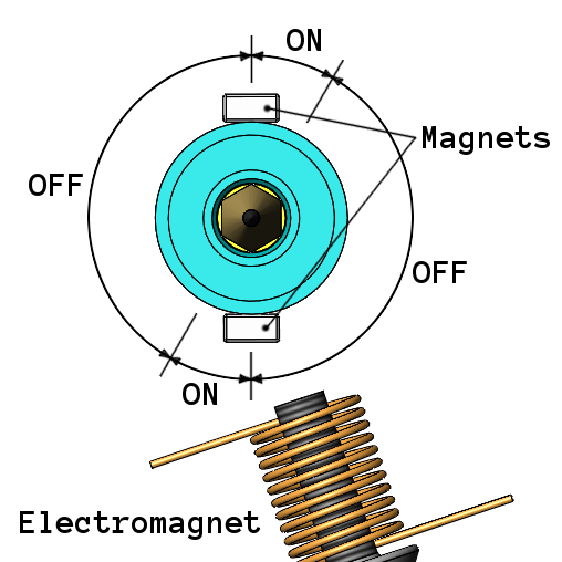
We want to turn the electromagnet on just after one of the rotor magnets passes the bolt. After a little bit of travel, say 30 degrees or so, it should turn back off. How can we do this switching electronically?
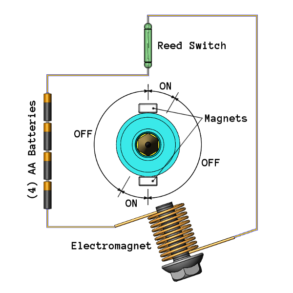
We chose a reed switch to tell us when the magnets are in the right position. A reed switch is a glass-encased sensor, where two ferromagnetic leads are almost touching one another. Apply a magnetic field to the sensor with just the right strength and direction, and it causes those two leads to touch one another. It makes electrical contact, like a switch turning on.
A Hall effect sensor is probably a more appropriate choice for a motor, but we wanted use a reed switch because of its simplicity. It’s a very simple device, where two wires connect or don’t connect.
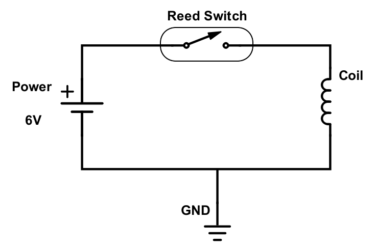
With the reed switch positioned as shown, it makes contact only during the correct portion of the rotor’s rotation. In theory, this simple circuit should control our setup nicely.
While the setup above worked briefly, we quickly ran into problems. If you run a lot of current through a reed switch, it can arc, welding the two wires together. This is especially true if the load is an inductor. What’s an inductor? Think of a coil of wire, just like we’re using here…
Having a problem with an arc isn’t too surprising. After all, we’re essentially shorting out the batteries, running a current through a pretty short length of wire. Common sense would expect a little spark when they make contact.
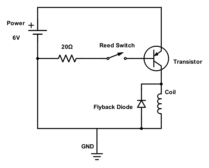
To fix this problem, we added a transistor to the circuit. Instead of having all the electromagnet’s current go through the reed switch, we used the reed switch to trip the transistor on and off. The current goes through the transistor instead. The transistor is basically an on-off switch that can handle a bit more current. Ths new setup works without welding the reed switch closed.
Ironically, we chose the reed switch because we wanted to avoid this sort of circuit complication with a Hall effect sensor. Ah, the best laid plans of mice and magnet engineers…
The final setup includes that transistor, plus a diode to prevent backflow from the electromagnet. The, “flyback diode,” prevents the current from frying the transistor when it turns off.
With the electromagnet switching on only through a small portion of the rotation, the rotor spins continuously! Check it out in the video below.
We added an LED that lights up when the electromagnet is activated to help visualize what’s going on.
Instead of a bolt, motor windings are wrapped around steel structures that use insulated layers of steel. These insulated layers help reduce the losses associated with eddy currents generated in the steel by changing magnetic fields. The steel usually has some silicon in it, which improves the hysteresis to allow the magnetic field to build up more quickly. See Electrical Steel.
The steel-to-magnet distance is usually minimized, getting the most push out of a given magnet.
Most motors have multiple magnets and multiple windings. Often the windings will both push away the magnet that has passed it (repulsion, as we’ve done) and the winding ahead will pull the magnet towards it (attraction). All these improvements help improve the consistency of torque throughout the rotation cycle, rather than our simple system with two shoves per rotation.
Most motors don’t use reed switches. A Hall effect sensor is much more common.
Some motors don’t use a magnetic sensor at all. Some detect the electromagnetic field generated in the coil by the passing magnet to determine the magnet position. Neat! To learn more, look up, “sensorless BLDC motor.”
Yes! Older motor types have a wire, or a bunch of wires (like a brush) that makes contact during the times of the cycle where you want current to flow. They're called brushed DC motors.
Our Simplest Motor article is an example of a brushed motor. Electrical contact is made during some portion of the cycle by having two wires touch one another.
Disadvantages of brushed motors include both losses through the brush due to imperfect electrical contact, and issues with wear and tear.


 Cart
Cart