We are now required to collect sales tax in several states. Learn more about tax exempt status for your business.
Our original Halbach Array article focused on linear arrays, where a long row of magnets is used to make a strong magnetic field on one side. This time around, we’ll look at circular Halbach arrays, where a number of magnets arranged in a circle create interesting results.
Klaus Halbach was a physicist who invented and used these magnet assemblies to focus particle accelerator beams while working at the Lawrence Berkeley National Laboratory in the 1980s. The effect was actually discovered years earlier by John C. Mallinson, but Halbach’s use of them got his name stuck to it.
For some reason, these arrays fascinate folks searching for free energy or ways to get around Earnshaw's theorem and magically levitate magnets. Here we'll try and look into some of the more practical, hands on, less mystical features of these arrays.
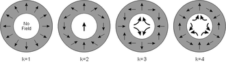
Circular arrays can produce a number of different effects, depending on how the magnets are arranged. A good place to start is this image from Wikipedia, depicting four different configurations. They’re labeled with a number k equaling 1 through 4, though what exactly k represents isn’t explicitly described there.
The image uses arrows to show the magnetization direction of 12 different magnets arranged around the circle. If you imagine yourself walking around the circle of magnets, the rotated direction of each magnet also rotates by some amount. In k=1, the rotation angle of the magnets goes around 360° in the same time it takes to walk around the circle.
In k=2, the magnets rotate faster. As you walk around the circle once, the magnet rotation circles around twice. That is, as you step 30° around the circle to the next magnet, you’ll find the magnetization direction turned 60° from the last magnet’s orientation.
Likewise, in k=3 the magnets rotate through three turns around as you go around the circle. Finally, k=4 goes through four turns. The k number expresses how many times the magnetization direction "turns around" as you go once around the circle.
Depending on what configuration you choose, you’ll see very different magnetic field strength and direction inside the circle.
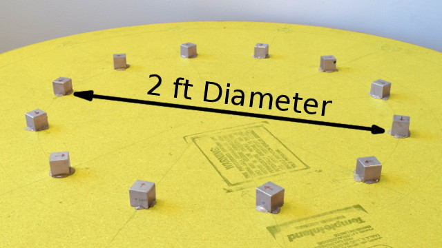
We created a k=2 Halbach array with a dozen BX0X0X0-N52 1” cube magnets, arranged in a 2 ft diameter circle. This setup gives us a field strength of about 12 gauss in the center of the circle.
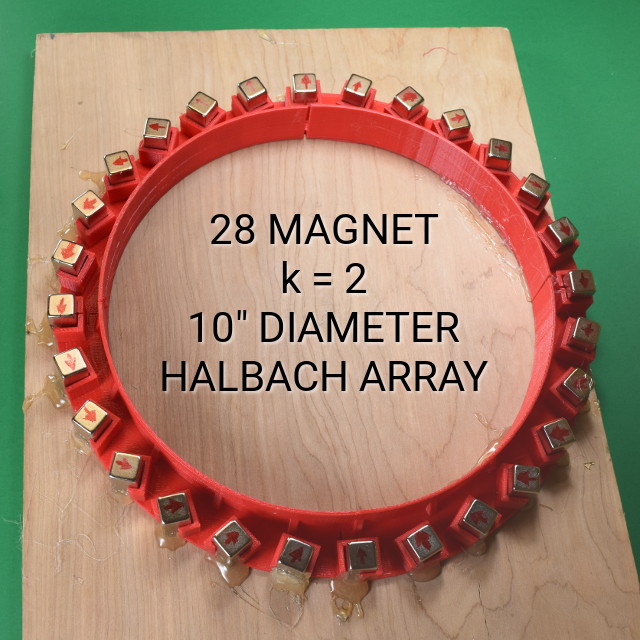
We created a second k=2 array with a smaller, 10” diameter. With 28 BX088-N52 magnets, each 1” x ½” x ½” thick, this resulted in a 73 gauss field strength at the center. The greater number of magnets set in a smaller ring provided a stronger field strength. The effect of a uniform field is quite similar, though.
The arrays we’ve shown here have relatively low strengths. There are applications where much higher field strengths are achieved with more magnets and/or bigger magnets, squished closer together. It can be an expensive assembly of magnets, dangerously difficult to assemble. Still, it can be a better solution than an expensive electromagnet that requires a lot of electricity. These things provide a strong field without any power at all.
How do people adjust the field strength on something like this? What if they try to build a 5,000 gauss system, but the result measures 4,975 or 5,050? The answer is more Halbach arrays. By nesting one array inside another, the fields add and subtract.
When we stick our smaller 12 gauss array inside the larger 73 gauss array, we find that the field strength inside can vary depending on their rotations. It can be as low as 73 – 12 = 61, as high as 73 + 12 = 85, or something in between.
When you dig into the math of this setup, the way it all adds together is quite interesting. Each magnet you add around the circle contributes some magnetic field strength at the center in both the vertical and horizontal directions. The funny thing is that all the horizontal components tend to cancel each other out in this arrangement. That's why the field direction is purely vertical.
On the other hand, each contributes some magnetic field strength in the vertical direction, all pointing the same way. It's a slick, elegant solution.
Let’s try one more thing with our uniform magnetic fields. A magnet’s dipole moment is a measure of its strength. It tells us how much torque a magnet will feel when placed in a uniform magnetic field.
The very definition of the dipole moment (explained in more detail in our Unit Converter) is how much torque a magnet feels when placed in a uniform magnetic field. The units give it away: N m / T. That's Newton meters (the torque, force times distance) per Tesla (the field). Let’s stick a few magnets in the field, measure the torque and see if it matches what we expect!
Note: Our Measuring Magnets article mentioned how to measure the dipole moment by measuring the current induced in coils of wire when moving a magnet around inside them. Those measurements are much more accurate, but measuring torque directly seems more fun for this article!
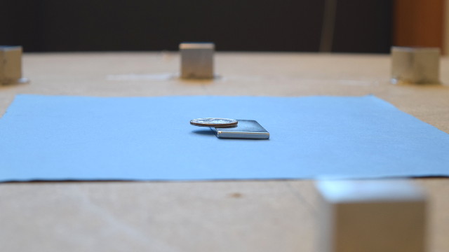
When you place a magnet inside the array, into that strong uniform field, it feels a torque from the magnetic force. It’s just like how the earth’s magnetic field rotates a compass needle, only stronger. The video below shows how this torque can flip a magnet up to make it stand on edge. In many cases, this magnetic torque is strong enough to overcome gravity trying to pull the magnet down flat.
By stacking some coins on the edge of the magnet, we made a rough check of the magnet’s dipole moment. It’s a pretty rudimentary test, but we like how it relates directly to feeling a torque in a field.
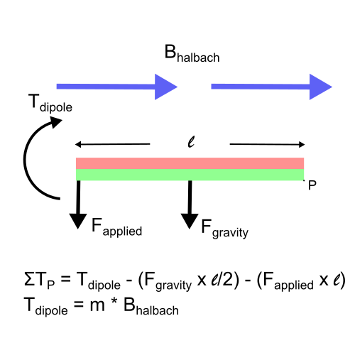
With a quick, mechanical-engineering-style statics study, we made some predictions about how much mass is required to hold it down. We used some loose change for mass. Let's see how we did.
| Part No. | Size (in) | Orientation | Required Mass, Theoretical (g) | Required Mass, Experimental (g) |
| BX0X02 | 1" x 1" x 1/8" | square magnet (same either way) | 2.7 |
< 4.5 (2 dimes) |
| BX0X04 | 1" x 1" x 1/4" | square magnet | 5.4 |
< 7.9 (1 quarter + 2 dimes) |
| BX082 | 1" x 1/2" x 1/8" | short side of rectangular magnet aligned with field | 6.5 |
< 7.9 (1 quarter + 2 dimes) |
| " | " | long side of rectangular magnet aligned with field | 1.3 |
< 2.3 (1 dime) |
| BX084 | 1" x 1/2" x 1/4" | short side... | 13 |
< 17 (3 quarters) |
| " | " | long side... | 2.7 |
< 4.5 (2 dimes) |
| BY0X01 | 2" x 1" x 1/16" | short side... | 2.7 |
< 2.3 (1 dime) |
| " | " | long side... | -2.5 | |
| BY0X02 | 2" x 1" x 1/8" | short side... | 5.4 |
< 6.8 (3 dimes) |
| " | " | long side... | -5 | |
| BY0X04 | 2" x 1" x 1/4" | short side... | 10.7 |
< 10.2 (1 quarter + 2 dimes) |
| " | " | long side... | -10 | |
| BZX082 | 4" x 1/2" x 1/8" | short side... | 24.2 |
< 30.6 (5 quarters + 1 dime) |
| " | " | long side... | -10.4 |
Reading through the table, it looks like the theoretical predictions held up pretty well. They don’t match perfectly to the tenth of a gram, but it’s not bad considering how rough the measurement is.
Interestingly, the theory predicted negative numbers for some rectangular magnets oriented in the long direction. This indicates that the pull of gravity on the magnet is stronger than the magnetic torque. Even without any coins stacked on top, the magnet should lay flat. These predictions proved correct when we tested it. Physics still works!
UPDATE: Some readers have asked for the files used to 3D print the magnet holders we used here. They might not be perfect, but you're welcome to use them!
These three files are shapes for the 3" diameter, black arrays for k = 1 through 4. These use twelve 1/4" cube magnets each like the B444 or B444-N52 block magnets.
This file is one quarter of the red circle used in the 28 magnet array. It used 28 BX088-N52 block magnets.


 Cart
Cart