We are now required to collect sales tax in several states. Learn more about tax exempt status for your business.

A few years ago, we constructed Audio Speakers using plastic cups, coils of wire and magnets. They’ve never won any audio awards, but remain a popular demonstration. When we talk about how a current flowing through a wire in a magnetic field exerts a force, most of our audience starts drifting. Play some music through it, though, and suddenly everyone wants to know how it works!
We’ve enjoyed how a simply constructed experiment highlights some electrical engineering basics in a way that even kids understand.
In this sequel article, we want to reverse what’s going on with those speakers. Can we make a microphone using a plastic cup?
You can read about our previous speaker adventure here, but here’s a quick recap: The cone of a speaker moves quickly back and forth, producing sound. In our plastic cup speakers, a coil of wire is taped to the bottom of the cup, while a strong, stationary magnet sits nearby. When current flows through that coil of wire, it moves, because it’s acting like a little electromagnet. It attracts to or is repelled by the nearby magnet. This motion wiggles the back of the cup to make sound.
In the presence of a magnetic field (provided by the magnet), a coil of wire with a current flowing through it will feel a force. That force is what moves the speaker.

Back in the 1800s, scientist Michael Faraday figured out how this relationship between magnetism and electric current works both ways. Just as a changing electric current can induce magnetism in the coil, if you move the coil back and forth manually you’ll create a current in the wire. Theoretically, it should work like a microphone!
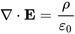
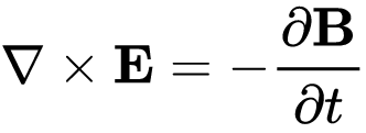
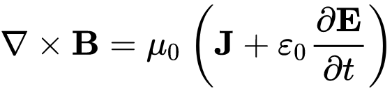
Later, James Clerk Maxwell built upon the work of Faraday and expressed it mathematically in a set of equations that describe electromagnetism, linking electricity, magnetism and light. If you’re a fan of the fancy computer simulation pictures scattered on our site, you have Maxwell to thank – they’re all based on those same equations.
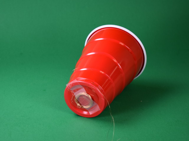
Since we already had a set of speakers, we tried using those backwards first. What happens if we just try using one as a microphone? Well, we found the signal far too weak. The speaker has a coil of wire made up of 150 turns of 30 gauge magnet wire, taped to the back of a plastic cup. We saw a tiny signal on the oscilloscope, but not nearly enough to drive a speaker.
Faraday’s law suggests that the voltage coming out of the coil should be directly related to the number of turns. More turns should mean more voltage, right?
We tried 600 turns, four times the number of turns in the speakers. With the same wire, though, that coil might be too heavy. We selected the very thin, 42 gauge wire we used back in our Electric Guitar Pickups article. It’s a challenge to work with since it’s as thin as hair, but it’s great for getting lots of turns in a tiny space.
With the new coil taped to the back of a cup, the response was stronger. Maybe we’re on the right track!
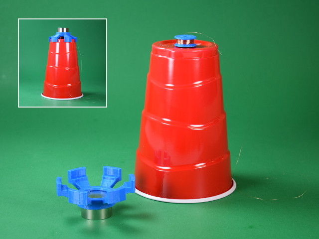
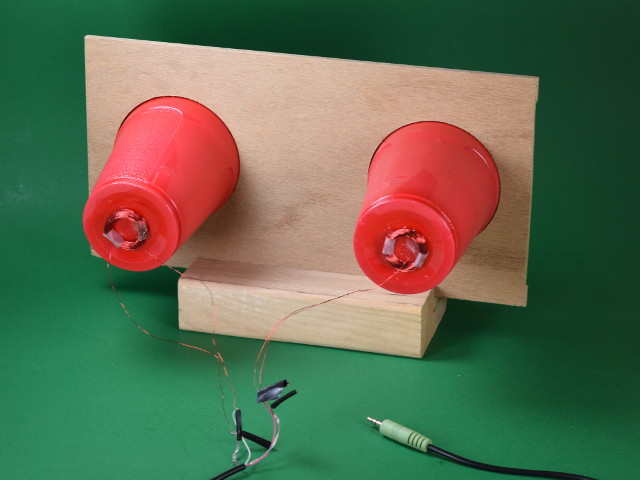
Wanting to knock this one out of the park, we again increased the number of turns. We wound 1500 turns of 42 gauge magnet wire onto a little plastic spindle we 3D printed and glued to the back of the plastic cup. A second 3D printed part formed a bracket that holds the powerful, 1 inch diameter DX0C disc magnet a short distance away from the coil.
For the curious, here are the STL files for the spindle and the bracket.
We hoped this would magically increase the signal strength, but it didn’t turn out that way. Apparently, building a microphone is a bit more complicated. Still, it conveyed sound from our voices the most clearly of all these microphones, so it has promise.
We get sound out of this microphone, but it’s too weak. If we plug this coil into a circuit that amplifies the signal, it should get louder. We need an amplifier!
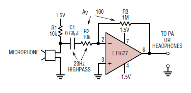
Not wanting to destroy any music amplifiers, we constructed a quick DIY amplifier circuit from parts we had on hand. (If you’ve been following us for years, you’ll recognize that we used the same amplifier chip from the circuit in the seismometer we built a few years ago.) It isn’t the greatest audio amplifier, but it sure did increase the signal strength.
The amplifier introduced a high pitched buzz, but definitely increased the signal/volume from the microphone. There’s also a lot of noise when we spoke too loudly, putting the amp, “in clip.” Even with all that, it was our best sound yet. It’s possible to make a working microphone this way!
Obviously, this isn’t a quality microphone. Plastic cups don’t make good sound receivers, and our hack electronic skills leave a lot to be desired. Even so, the basic concept is sound, showing the inner workings of how a microphone works. Maybe in the future we’ll get this working well enough to talk into the microphone and play out of our plastic cup speakers!
A few folks here want to try making a DIY ribbon microphone – but that’s a project for another day.


 Cart
Cart