We are now required to collect sales tax in several states. Learn more about tax exempt status for your business.
From time to time, we build contraptions to highlight some magnetic principle or application. Our DIY builds aren’t always pretty, but we find them useful to demonstrate concepts in a tangible way. Sometimes they become the inspiration for someone’s next science project. This is one of those stories.
It all started with a simple question: Can you build an ammeter out of a magnet? An ammeter is a device that measures electrical current flowing through a wire.
Well, sure, that ought to be possible. This gets back down to basics, the stuff Hans Christian Oersted observed: A current flowing through a wire induces a magnetic field. Can we make a device we can calibrate and measure current with?
UPDATE: We originally wrote that Michael Faraday discovered this. In fact, Faraday discovered that the opposite is true about a decade later: A magnet moving near a wire can induce a current in it.
To stay safe, we limited ourselves to modest DC currents, from 0 to 100 milliamps. While the classic intro picture to Faraday’s ideas show a magnetic field around a straight length of wire, we would need much larger currents to influence a nearby magnet.
A coil of wire with many turns creates a stronger magnetic field. When electrical current flows through the wire, it produces a magnetic field whose direction is along the axis of the coil. The expected field strength at the center of the coil is related to the current flowing through the wire and the number of turns.
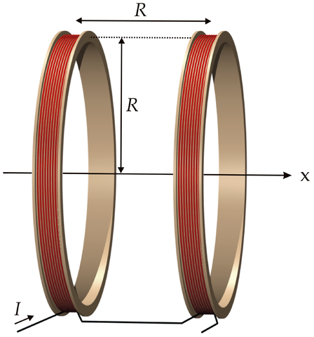
A single coil would work, but field measurements can vary with small changes in position. Slight changes in where you measure the field can give different results. There is a coil configuration that provides a fairly uniform magnetic field (in strength and direction) across a broad volume of space: Helmholtz coils.
By winding two coils spaced one coil radius apart, we get a nice, uniform magnetic field across a large portion of the center. We mentioned these coils briefly in a previous article about measuring magnets. In that application, we measured the current induced in the wire by turning a magnet around in the center. Today, we’re doing the opposite. We’ll push current through the wire to move a magnet sitting in the center of the coils.
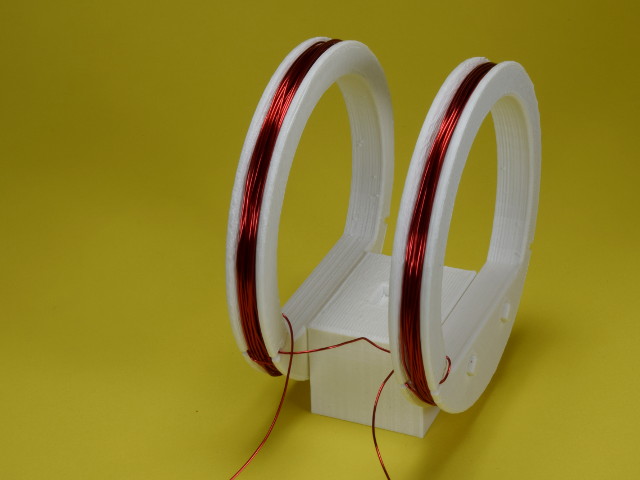
For this experiment, we 3D printed two 3” diameter coils, spaced 1.5” apart (files here and here). If you don’t have access to a 3D printer, you can build your structure out of whatever non-magnetic materials are available.
We wound two dozen turns of 24 gauge magnet wire (MW24-4 or MW24-8) around each coil, with both coils wound in the same direction. Using the field strength in Helmholtz coils equation, we can estimate the induced field strength in the center.
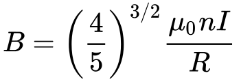
In the formula:
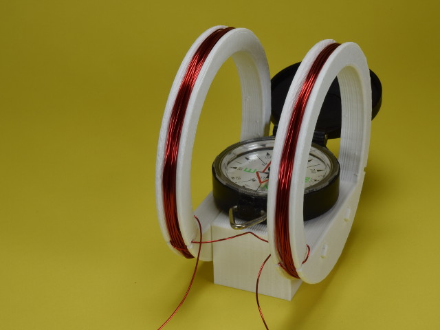
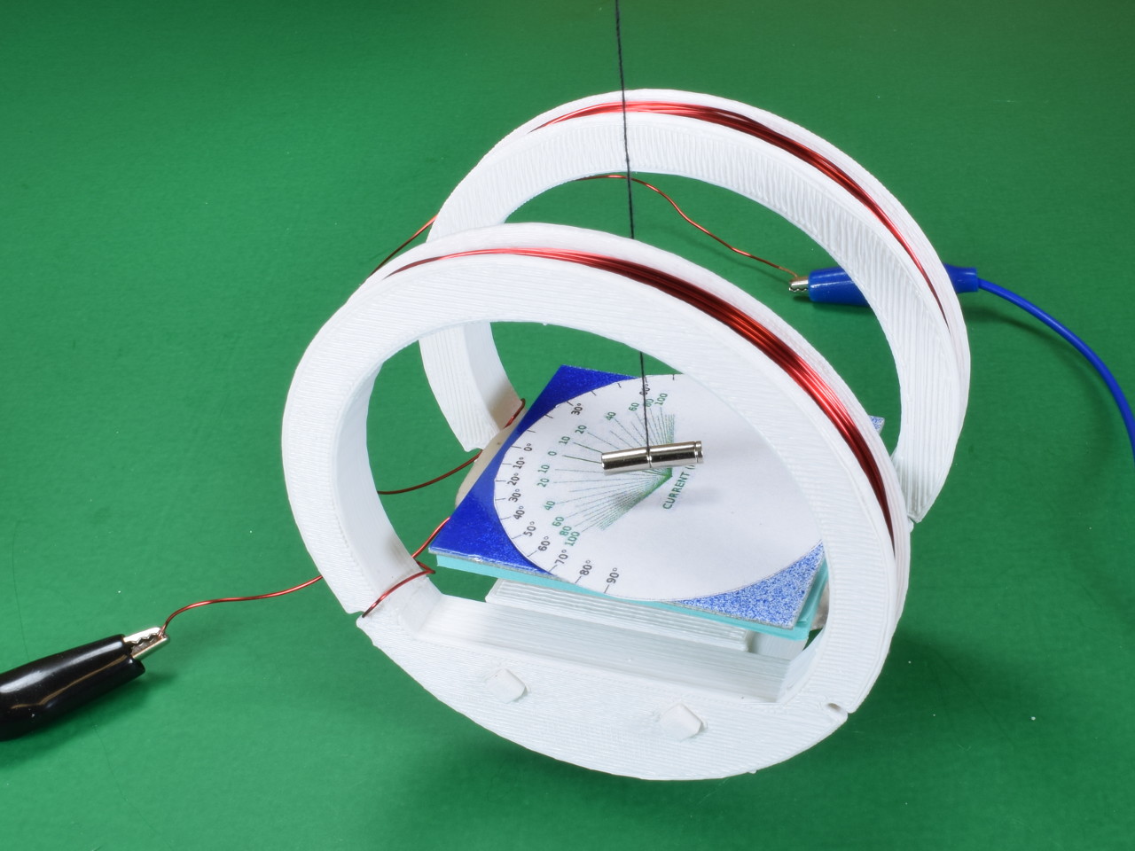
For our initial test of the device, we set a magnetic compass in the center of the coil. It’s a good indicator of magnetic field direction! With no current running through the coils, we aligned the coil axis on an east-west line.
At rest with no current, the needle of the compass points north. If we ran a gazillion amps through the coil, we would expect the needle to turn east or west, depending on the direction of the current.
In practice, the field direction at the center is the combination of the two fields. There’s the earth’s field pointing north, and the coil’s field pointing east or west. Summing the two, we can predict how much the compass needle should deflect as a function of how much current goes through the wire. That's exactly what we need to turn this into a working ammeter.
The 3 images show:
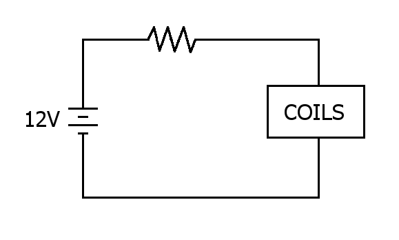
A power supply removed from an old PC provided a steady source of 12V electricity. We run that through a resistor and the coils. With a bit of electrical math, we estimate the theoretical field strength produced by the coils.
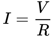
| Voltage (V) | Resistance (Ω) | Current (mA) | B (gauss) |
| 12 | 100 + 1 | 118.9 | 0.67 |
| 12 | 220 + 1 | 54.3 | 0.31 |
| 12 | 470 + 1 | 25.5 | 0.14 |
| 12 | 790 + 1 | 15.2 | 0.09 |
The plus one in the resistor column represents the added 1 ohm resistance of the coil.
Of course, the magnetic field created by the coil is only half of the story. The total field is a combination of that from the coil and the contribution from Earth’s magnetic field. What’s the field strength of the earth’s magnetic field? Here in Pennsylvania, the magnitude is around 0.5 gauss.
The trick is that the 0.5 gauss isn’t all pointing north, in a direction horizontal to the floor. It’s angled pretty sharply downward.
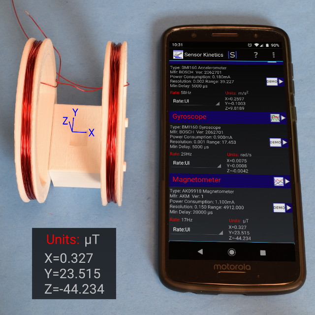
Using a smartphone and a special app that displays the raw output of its magnetic sensor (Sensor Kinetics iOS, Android), we measured the horizontal-to-the-ground (northward direction that will oppose the coil) as more like 0.24 gauss. (Convert microtesla to gauss here.)
With a compass sitting in the center of the coil, it shows the vector sum of Earth’s ambient field and the east-west field produced by the coils. We read the compass deflection and translate that into an amount of current.
With no current, the compass needle points north. With infinite current, the compass needle would point east or west, depending on the direction of the current.
With currents in our 0 to 100 milliamp range, the needle will point at some angle between north and east/west. The farther away from north that needle lands, the more current we must have running through the wire.
Wait a second – there aren’t any magnets here! I thought we were going to make an ammeter with neodymium magnets.
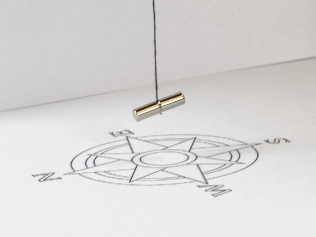
By sandwiching a length of string between two small D24 cylinder magnets, we made our own compass. The wobbling magnets on a string point north.
Unlike our compass, which has a needle suspended in a liquid, our magnets-on-a-string compass has very little damping. Bump it, and it wobbles back and forth a long time before settling down. To add damping, we placed a small piece of aluminum below the magnet.
As described in our Eddy Current articles (links) and our Seismometer project, the nearby conductor has currents induced it in when the magnet is moving, which act in the opposite direction. It’s a nice, simple damping mechanism that avoids messy complications with liquids.
When we place the magnets on the string, we notice that the north end leans down lower than the south end of the magnet. Why is this? It isn't because one magnet is heavier than the other. It’s because the suspended magnet is trying to align itself with the downward pointing magnetic field. Unlike the constrained compass needle, the dangling magnet is free to tilt downward as well.
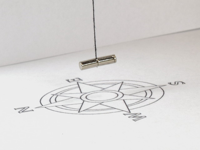
To help level it out, we added a tiny, 1/32” thick D201 magnet on the south side of the cylinder, to weigh it down a bit. It’s not perfectly level, but much closer now.
Note that this compass balancing process might be different depending on where you live. In Lima, Peru, the local magnetic field is almost perfectly horizontal, so no extra weight is necessary. Down in Melbourne, Australia, the tilt is just as much as we see in Pennsylvania but in the opposite direction. Australians need to add weight to the north end of the magnet to level it.
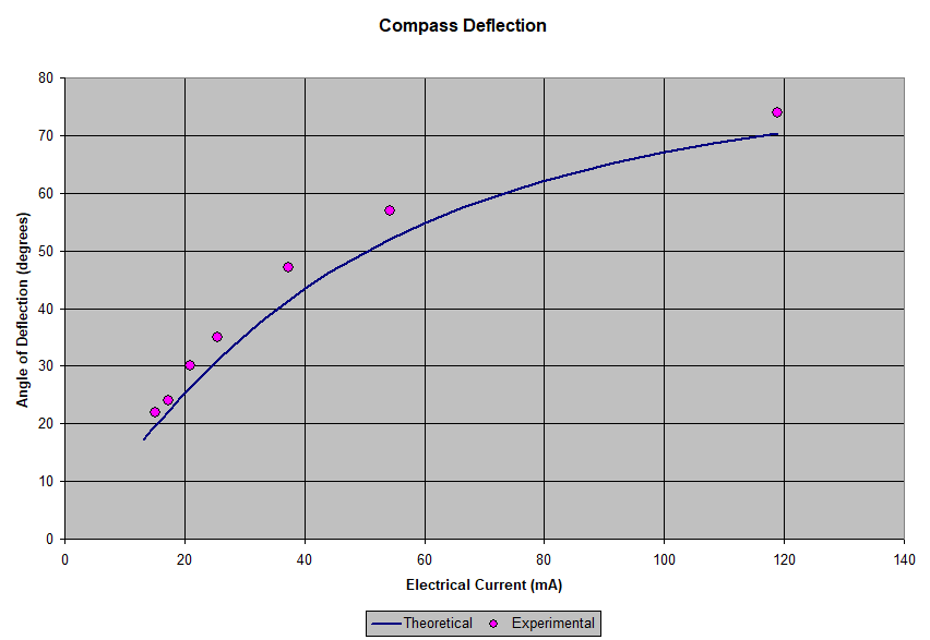
This device is hard to read with much precision, but our testing matched the theoretical predictions reasonably well.
The magnets we used in this device are small, 1/8” (3.18mm) diameter magnets. We used D24 magnets, and grabbed a few D201 discs for extra weight (though we only needed one).
There’s nothing unique about this particular size if you’re building your own string compass demonstration. We liked it as a good match for the size of the coils we constructed.
If you’re doing a compass demonstration in a classroom, where people need to see it from far away, consider larger magnets that are more visible from a distance. We’ve used larger, 3/8” or 1/2” diameter magnets for classroom demonstrations. See cylinder magnets like D6X0 or D8X0.
I’m making my own Helmholtz coil. What wire should I use? We used Magnet Wire, which is single strand, copper wire with a very thin insulating coating. It’s commonly used for things like transformers or motors, where you want to wrap a bunch of turns of wire in a tight space. You could use regular insulated wire if you have some, but the bundle is going to be a bit thicker since it has thicker insulation.
We picked 24 gauge wire (MW24-4 or MW24-8), because it was a nice size to handle and didn’t have a problem with the currents we used. Though the exact limit depends on many factors, this gauge is alright for currents up to 500-600 mA. If we were measuring larger currents, we would pick thicker wire.
We didn’t pick 30 gauge, because its limit of around 140 mA was too close to what we were measuring. Melting insulation is bad.
Thanks for reading along with us! If you do make something similar, please email us and share a picture!


 Cart
Cart