We are now required to collect sales tax in several states. Learn more about tax exempt status for your business.
In previous articles, we've shown how magnets are used in different rotary applications, like motors or magnetic couplings, but magnets can also be used as gears. A magnetic gear is similar to a mechanical gear in function, but uses magnets instead of teeth. Let's take a look at how a magnetic gear works, then we'll build one!
What are gears anyways? A traditional mechanical gear consists of machined parts that mesh together to transmit rotational motion. Each gear has "teeth" machined into them, which is how they mesh together. Geared devices can change the speed, torque and direction of a power source.
Gears of different sizes produce a change in torque and rotational speed, thus providing some mechanical advantage through their gear ratio. If you had two gears, one being 4 times larger than the other, this would be a 4:1 gear ratio. For every one rotation of the larger gear, the smaller gear would rotate 4 times. Two or more meshing gears working together are called a gear train, or a transmission. In our build, we'll focus on just using two dissimilar gears to get some mechanical advantage, using magnets!
At some point, we've all have probably seen and used mechanical gears, even if it was way back in 5th grade science class. Similar to magnets, they're everywhere! Cars, bicycles, electronics, etc. Compared to mechanical gears, magnetic gears are seldom used, but to us, they're much more interesting!
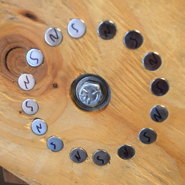
The gears don't touch at all, they only interact magnetically, which makes them very unique. The "gear ratio" is determined by the number of magnets used in each rotor. If one rotor has 4 magnets and the other 16, that's a 4:1 gear ratio.
There are four basic magnetic gear types:
First-order device: In this setup, both gears have the same number of magnets and they'll rotate at the same speed. This setup is basically just a magnetic coupling, but it allows for rotation to be transferred through non-magnetic barriers.
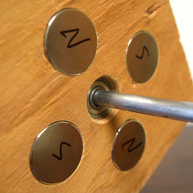
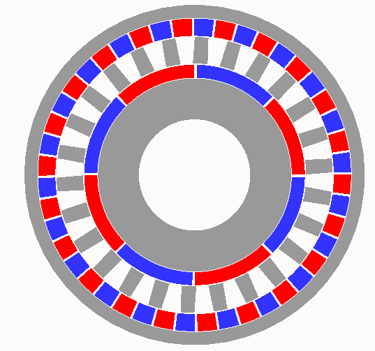
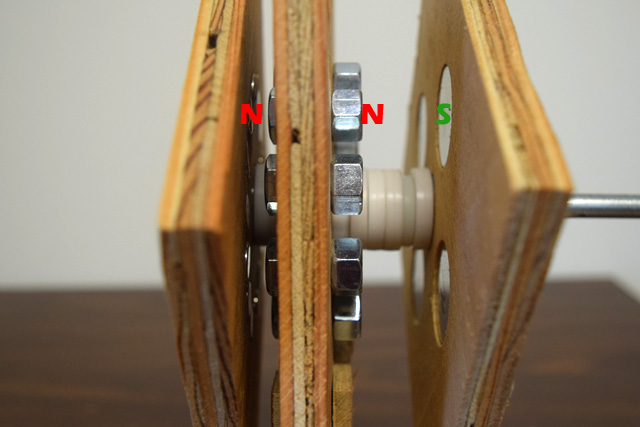
Second-order device: This setup uses a ratio of magnetic pairs between the inner and outer rotors, with ferromagnetic stators between them. Each gear has magnets with alternating polarities. As one rotor spins, it temporarily magnetizes the stator in the same direction, thus repelling or attracting the magnets on the other rotor. The rotor with less magnets rotates at a higher speed than the rotor with more magnets. You can change the number of stator pieces to have the gears rotate in the opposite direction (more stator pieces), or in the same direction (less stator pieces).
For an "opposite to input" motion, the number of stators is determined by the sum of the pole pairs in each gear. To move the gears in the same direction, the number of stators is determined by the difference between the number of pole pairs in each gear.
Our build will be a type of second-order device, but they'll be axially aligned with the stator pieces between them.
Third-order device: Similar to the second-order device, but is modified with external electromagnetic coils, which can create a variable transmission or variable gear ratio.
Fourth-order device: This device takes the third-device and modifies it further to have a low torque variable speed input, a high torque mechanical input and a high torque mechanical output. This is often called a torque multiplier.
Enough talk, let's try to build one of these devices! As mentioned, we'll build a second-order device, with the goal of having a 4:1 ratio, rotating in opposite directions.
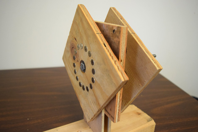
To simplify the design, we'll use two rotating discs with magnets embedded in them, rotating on the same shaft, with the stator pieces between them. To be transparent, in our research we saw a similar design on YouTube, and thought it was worth replicating. The video we saw used 3D printed pieces, but since not everyone has a 3D printer, we wanted to attempt making one the old-fashioned way!
Check out the video below to see how we built the device and to watch it work! Scroll below the video for a parts list and downloadable templates.
D62 magnets - quantity 32
DX22 magnets - quantity 8
3/8" x 3/4" long hex head screws with nuts - quantity 10
Bearing (any size) - quantity 2
Axle - quantity 1 (diameter should be slightly smaller than the bearing hole diameter).
Scrap plywood
Download the high-speed gear template here, low-speed gear template here, and the stator template here.


 Cart
Cart